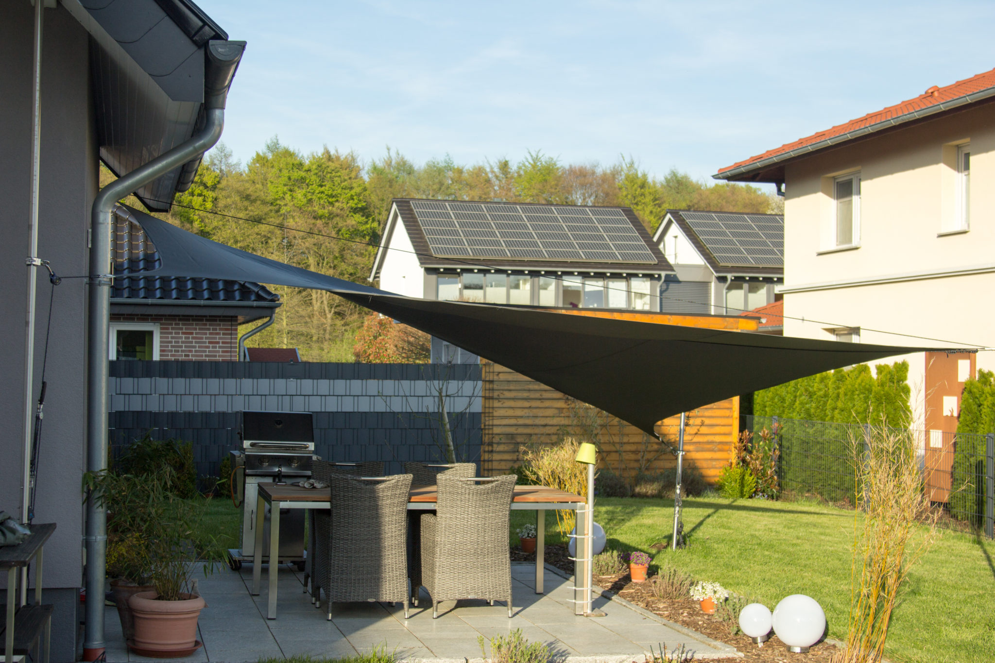
With this construction instruction for the roll-in solar sail, I show step by step how I completed the project!
In order to implement the concept, I first started with the procurement of materials. The most complicated – because custom-made – were the two brackets as stainless steel rods on the side of the house. In any case, stainless steel was mandatory for all metal parts. Looks good and is very weather-resistant. Since I have a buddy who "does in metal" I discussed this with him and commissioned it.
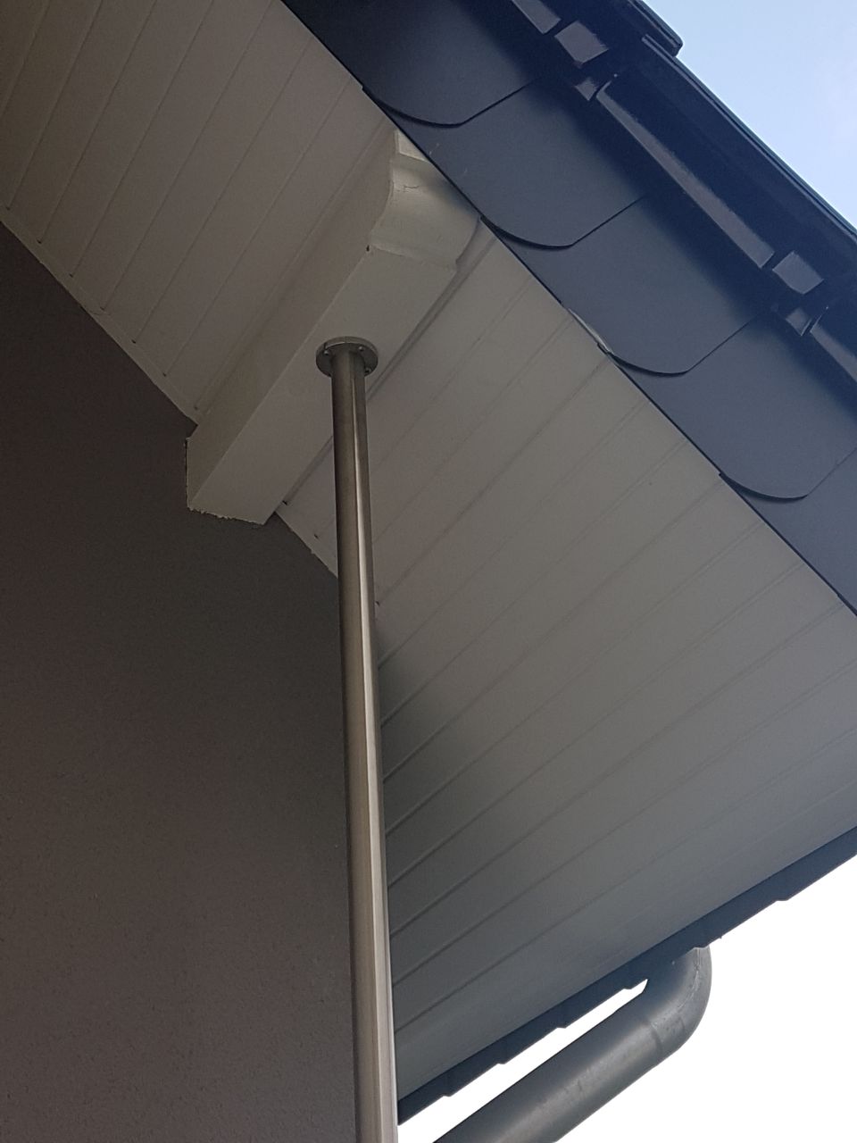
The brackets on the house
A pipe with 42.4 mm outer diameter and 2.5 mm material thickness serves as the basis for all holding rods. This is the thicker version. 2mm will probably be enough and is also significantly cheaper. In my case, I needed two 3.5 m long pipes. open at the lower end, at the upper end I had a solid, round stainless steel disc (10mm) welded with four holes for fastening to the wooden rafters.
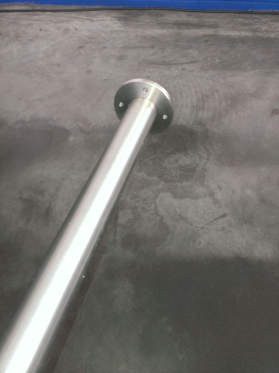
I then used stainless steel wooden screws to secure them loosely on the wooden rafters so that I could get the rod soldering. Subsequently, the hole was filled with screed concrete.
The brackets in the lawn
First, the position must be determined. The Pythagorean theorem actually helps:
a2+b2=c2 – so with my sail with 4×5 meters edge length: 16+25 = 41. 41 is c2, the root of 41 is the diagonal c = 6.40 meters. Amazing that you can use something from school… ;-). In addition to the diagonal, you now have to add the suspensions and the rewinding technology, as well as tolerances and travel. The axles are stretched later so that the sail does not hang; this travel must be added with. I have this travel at the axis around which the sail is later rolled, short sized: From one end to the other I have to plan the following parts into the length: bracket on the rod (5cm) -> Wantenspanner (35 – 18 cm) -> Carabiner (8cm) -> Fock Roller (8cm) -> Sail (6,40m) -> Vortex (5cm) -> Carabiner (8cm) -> Bracket on the rod (5cm) Together a diagonal of about 7.14 meters.

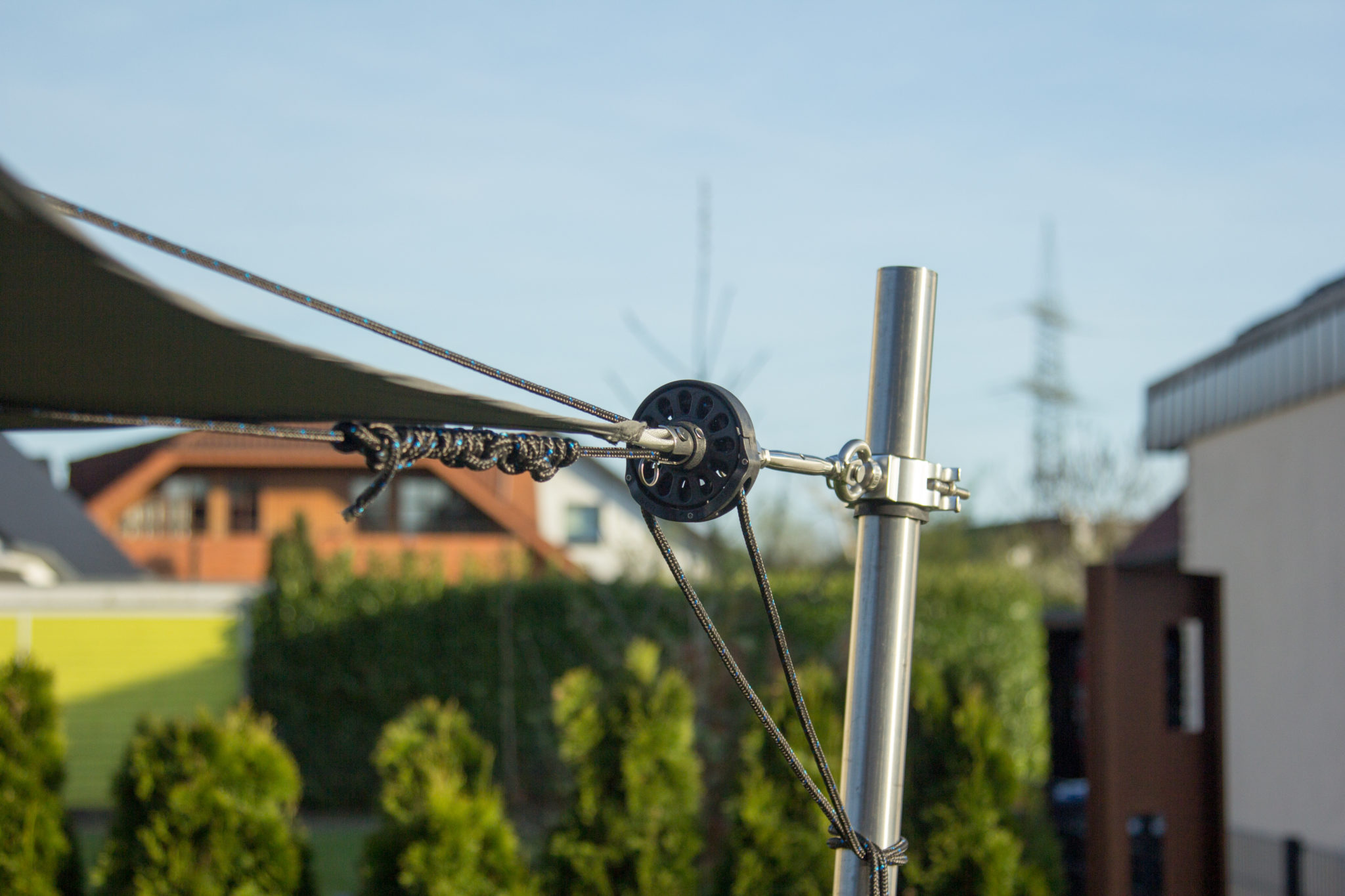
The brackets are actually made of event technology for stage trusses. I chose Global Truss truss recipients here. Make a valuable, well-finished impression and are made of stainless steel. For less than 10 EUR! More in the material list… In order to bridge the difference between the cross-sections and to prevent metal from being mounted on metal, I cut a hard rubber and clamped it between the stainless steel rod and the bracket. That's bomb-proof! The single bracket is certified up to 100 KG.
 </yoastmark>” />
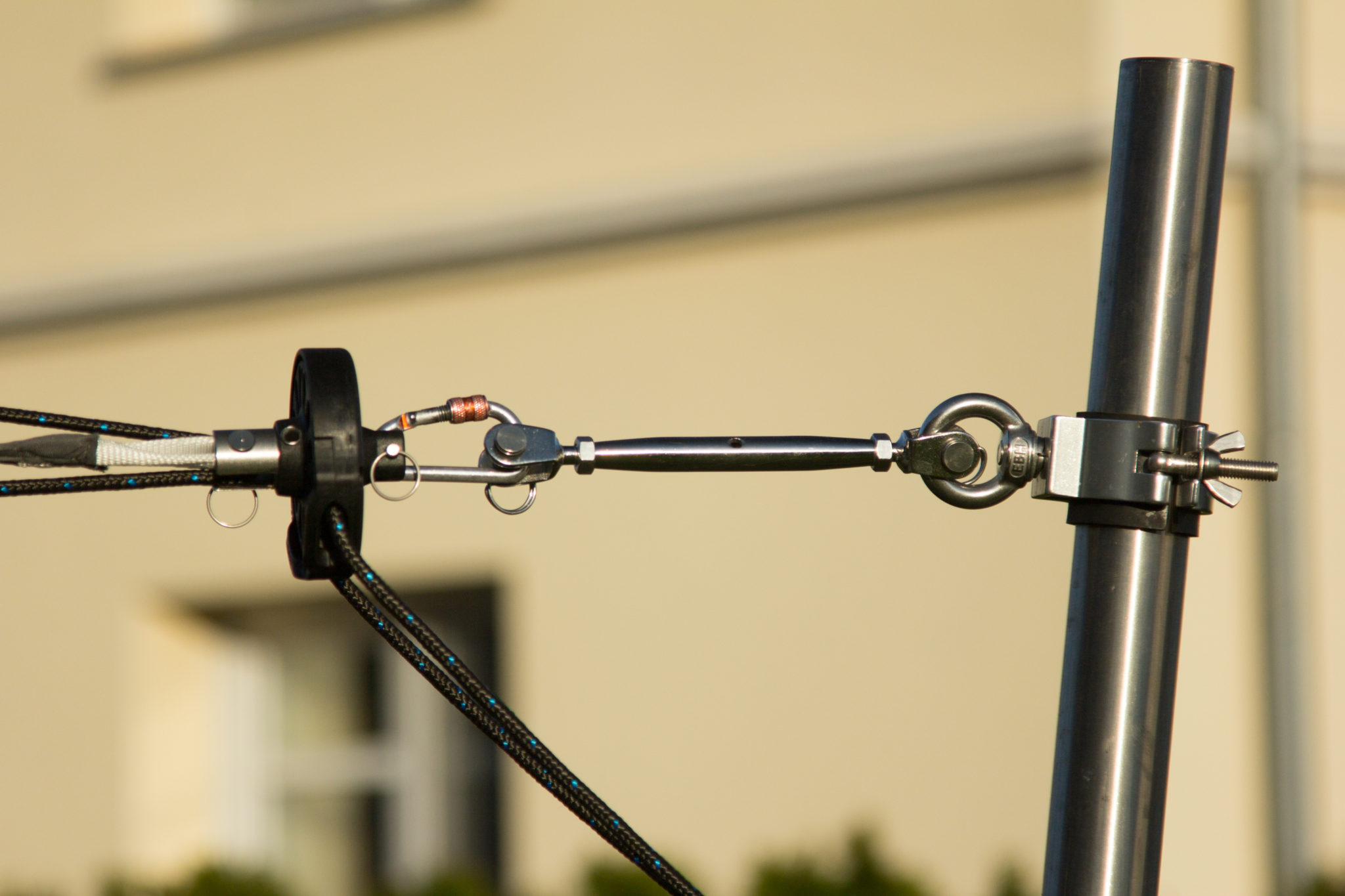 </yoastmark>” />
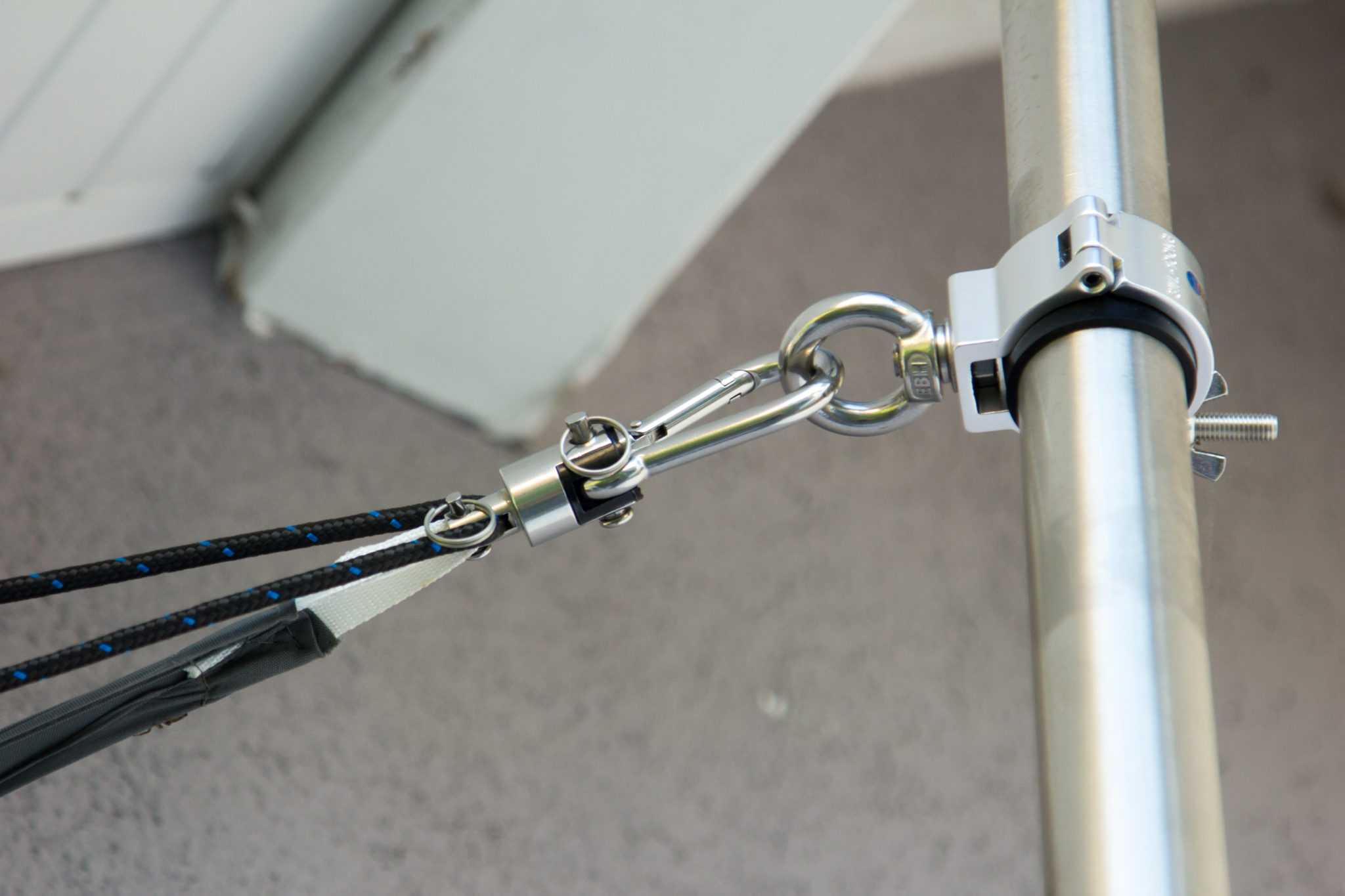 </yoastmark>” />
The second axis, i.e. that of the corners that are rolled up, should be measured more generously. The brackets are height-adjustable, so that the sail could be adapted to the state of the sun. Changing the height also changes the diagonal length. This axis has in addition to the diagonal of the sail (also 6.40 meters) two carabiners and I have the distance between rod and sail with approx. 1 meter. So I get in this diagonal at about 8.40m. The settled rods are therefore not arranged symmetrically, which does not really bother me.
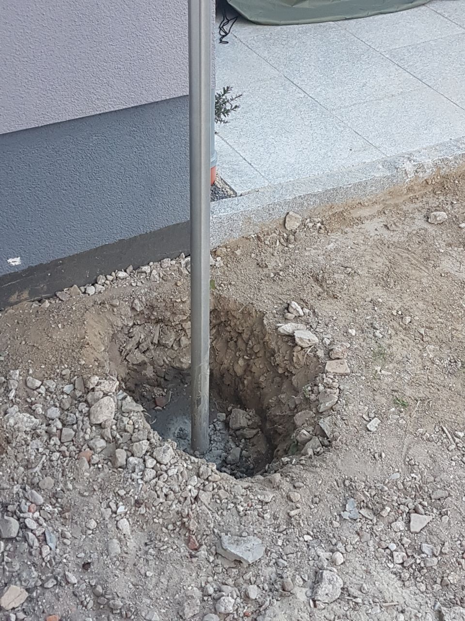
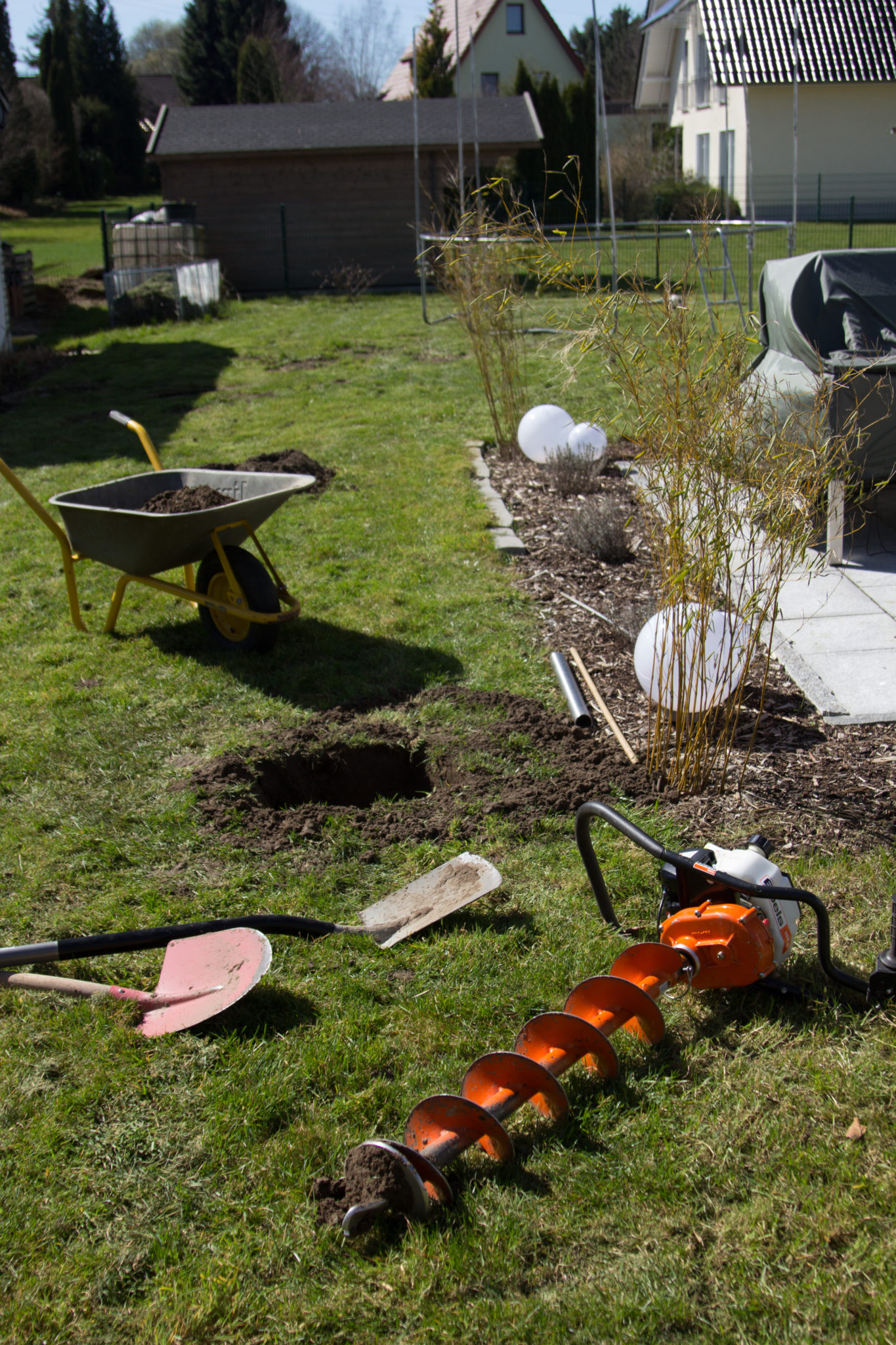
For the foundations of the rod one should adhere to the specifications of the sail manufacturer. I had a concrete foundation of 40x40x70 cm. The rod should be tilted away from the sail at an angle of 10° in order to obtain optimum strength. Since I did not want to concrete the rods myself firmly, I had matching sleeves cut (10° bevelled) x 65cm. The sleeve must of course have a larger diameter than the stainless steel tube. For me, the choice was 48.3 x 2mm construction pipe V2A. The hole for the foundation is not big now, but on the one hand difficult to dig with the spade (because narrow) and for manual operation quite deep. So I borrowed an earth drill, or I tried. I rattled off all the hardware stores, but no one had an earth drill left. So I had to ask a rental company, which were much more expensive… And apparently everyone wanted to drill holes this weekend. With luck I got another one, which a customer brought back much sooner than planned.
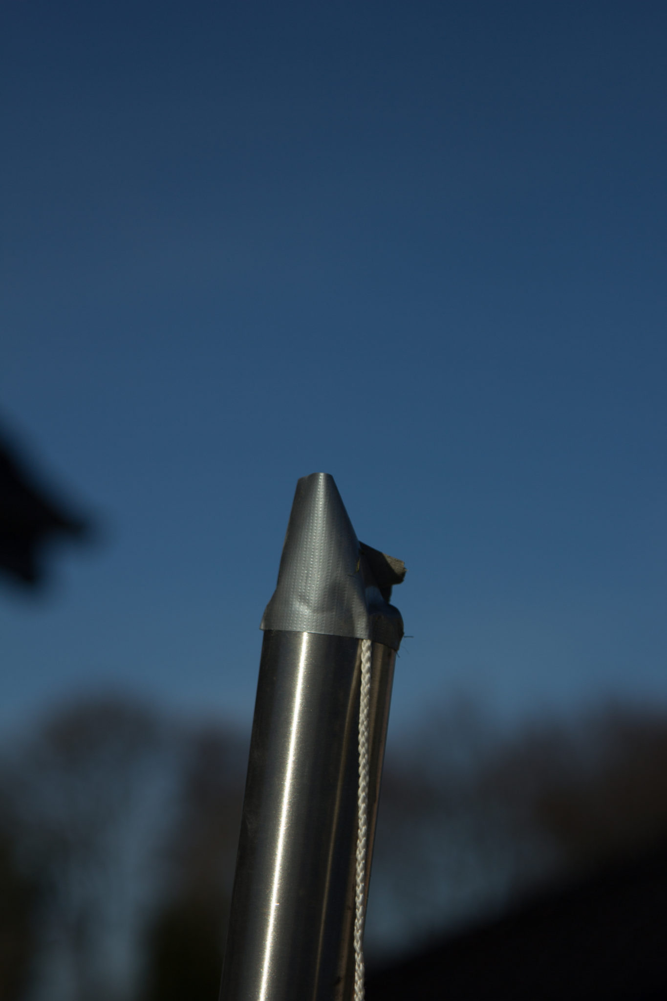
After digging the holes, I put the stainless steel tubes into the sleeves. I closed the pods at the bottom with a small plastic bag so that no concrete could penetrate from below. To determine the correct inclination, you attach a solder to the top end and then only need to measure the distance from pipe to the solder: With an incline formula and the online calculator, this works quite simply:

igure: https://rechneronline.de/steigung/
s = stainless steel pipe (measured from the ground)
l = lot
h = distance between stainless steel pipe and solder
The pipe is "above ground" 2 meters long. Thus, a distance of approximately 35 cm results.

Concrete pipes
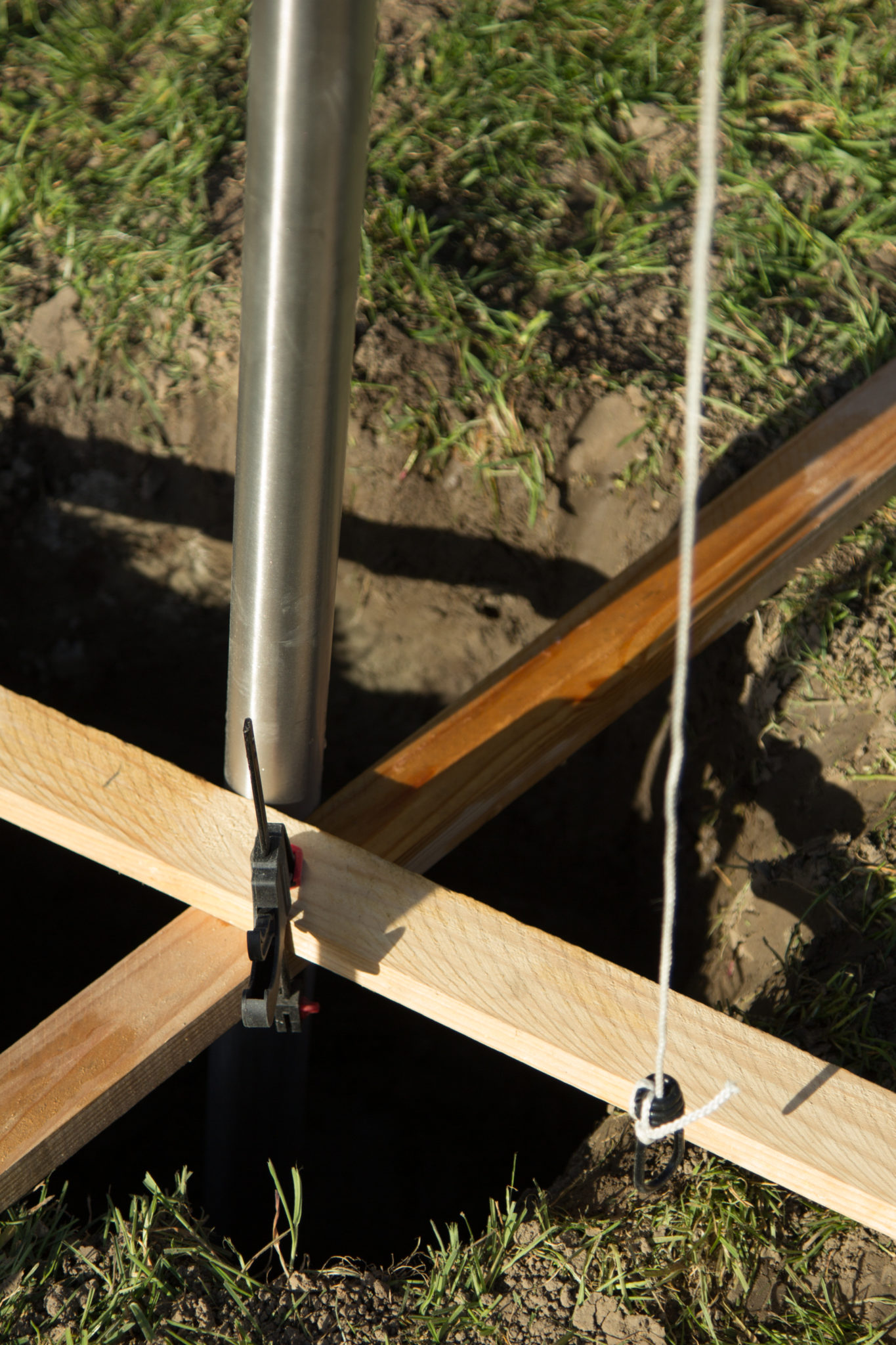
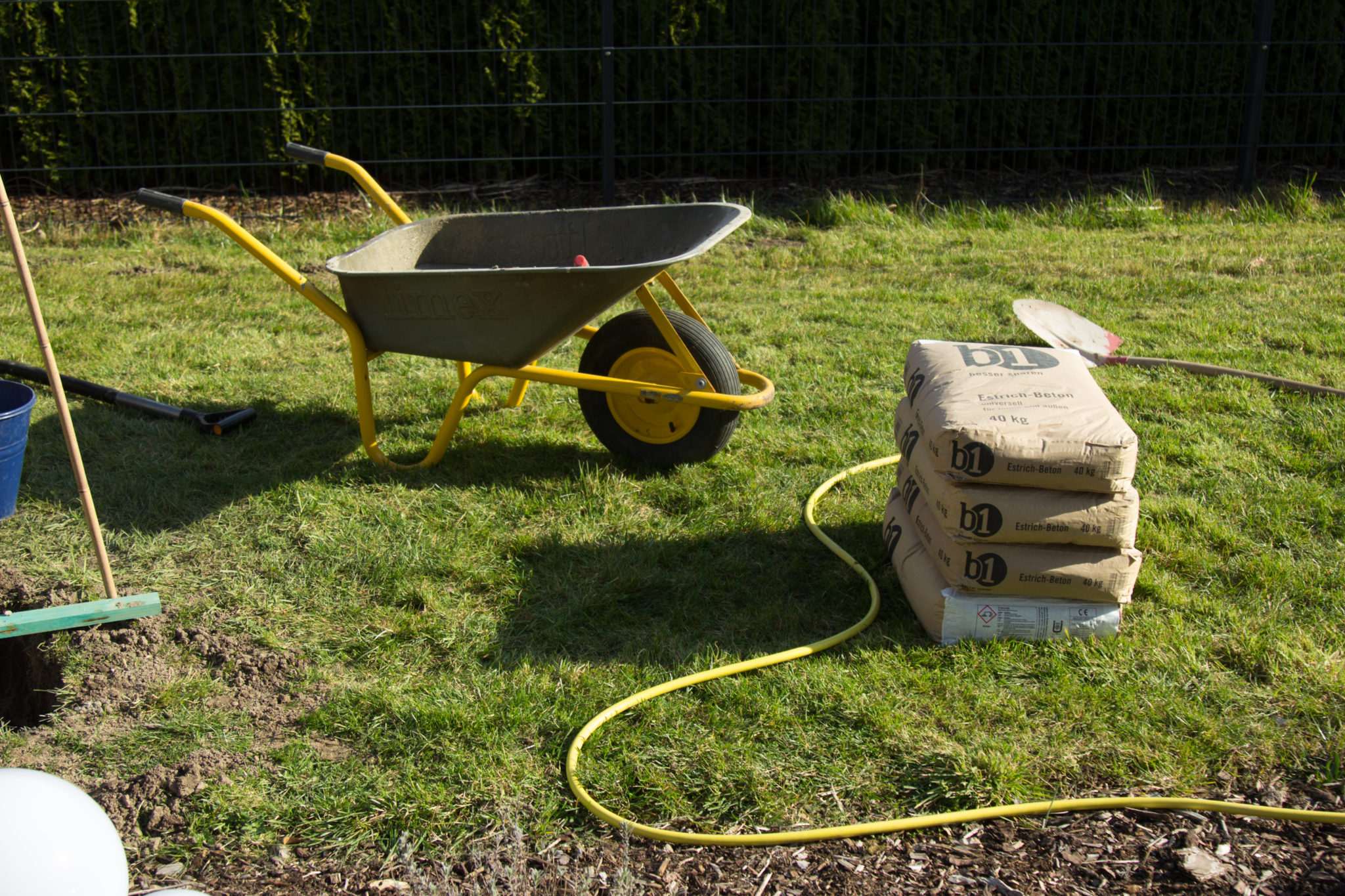
In order to fix the position, after measuring, I fixed the pipe with the help of two wooden slats and then with rapidly curing concrete. It pulls up after just three or four minutes and after ten minutes it is so firm that nothing changes at the position. For the rest I took screed concrete, as it is considerably cheaper. For the amount you have to calculate the volume of the hole. On the packaging or from the staff in the hardware store, you can find out how much volume a bag of concrete yields. A lot of things come together! In quantity and above all in weight. I had to drive with my station wagon twice, otherwise I would have got a free lowering kit 😉
I premixed the screed concrete in the wheelbarrow and then gradually filled it in. The drying time should not be underestimated. According to an architect, I was recommended at least five days (!) before the foundation was to be completely loaded. My sail measures about 4×5 meters. That's just under 20 square meters. There are great forces in the wind.
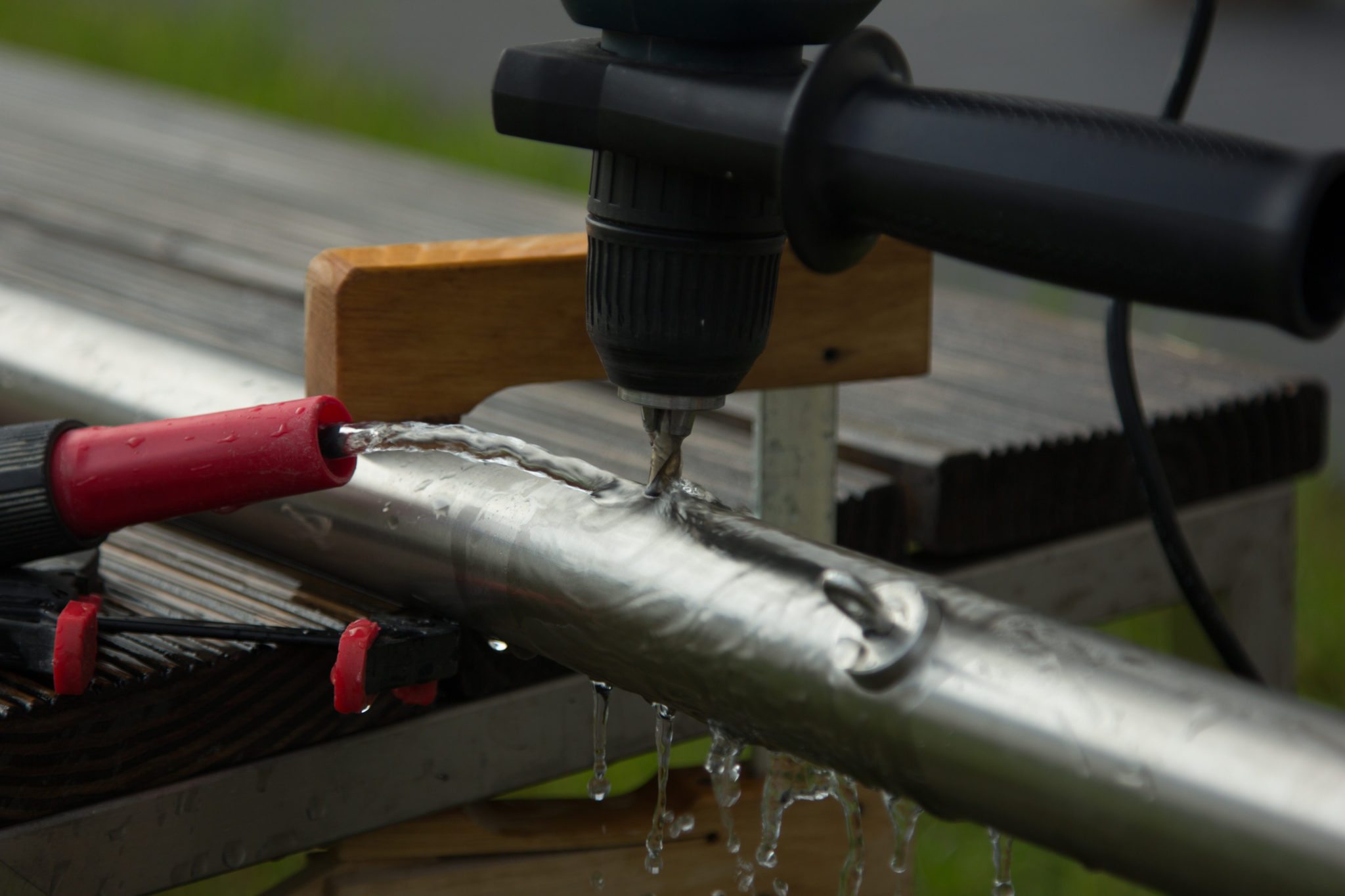
Preparing stainless steel pipes
Drilling for the clamps and the cable pull must be made to the two opposite pipes, where the rolled-out ends are fixed. The stainless steel stuff is damn hard! I got four drills through. Then back to the hardware store and bought a special drill for stainless steel – otherwise it won't be anything! And I strongly recommend water cooling, otherwise the expensive drill is dull after a hole. With a garden hose and a clamp, it's easy.
Assemble attachments

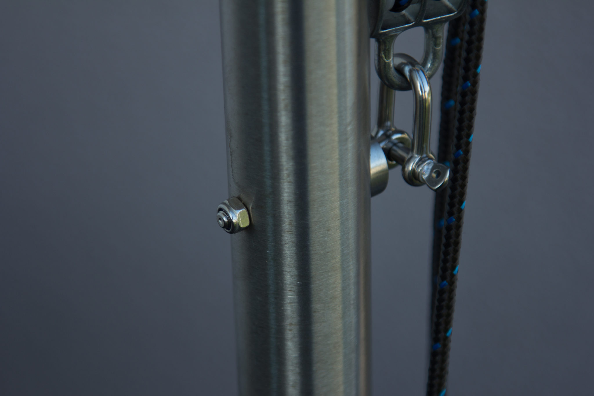
The eye screw serves as the fixing point of the shackle, which is the lower part of the pulley or of the Niederholer. I simply built the Niederholer from two double block rope rollers. The upper one is connected with a clamp, the lower one with the shackle.
This system is necessary to get enough pull on the rope so that the sail sits nicely tight. Finally, the brackets (truss bracket) for the rope deflection have to be mounted.

Rigging
First, I fixed the "roll-in axis". The vortex is mounted on the side of the house.

It is important to install the rope in the middle. The sail is later rolled around this rope and it is necessary to stabilize the sail on the axis so that it does not hang through.
The rewinding mechanism, the fock roller, is attached to the opposite side.


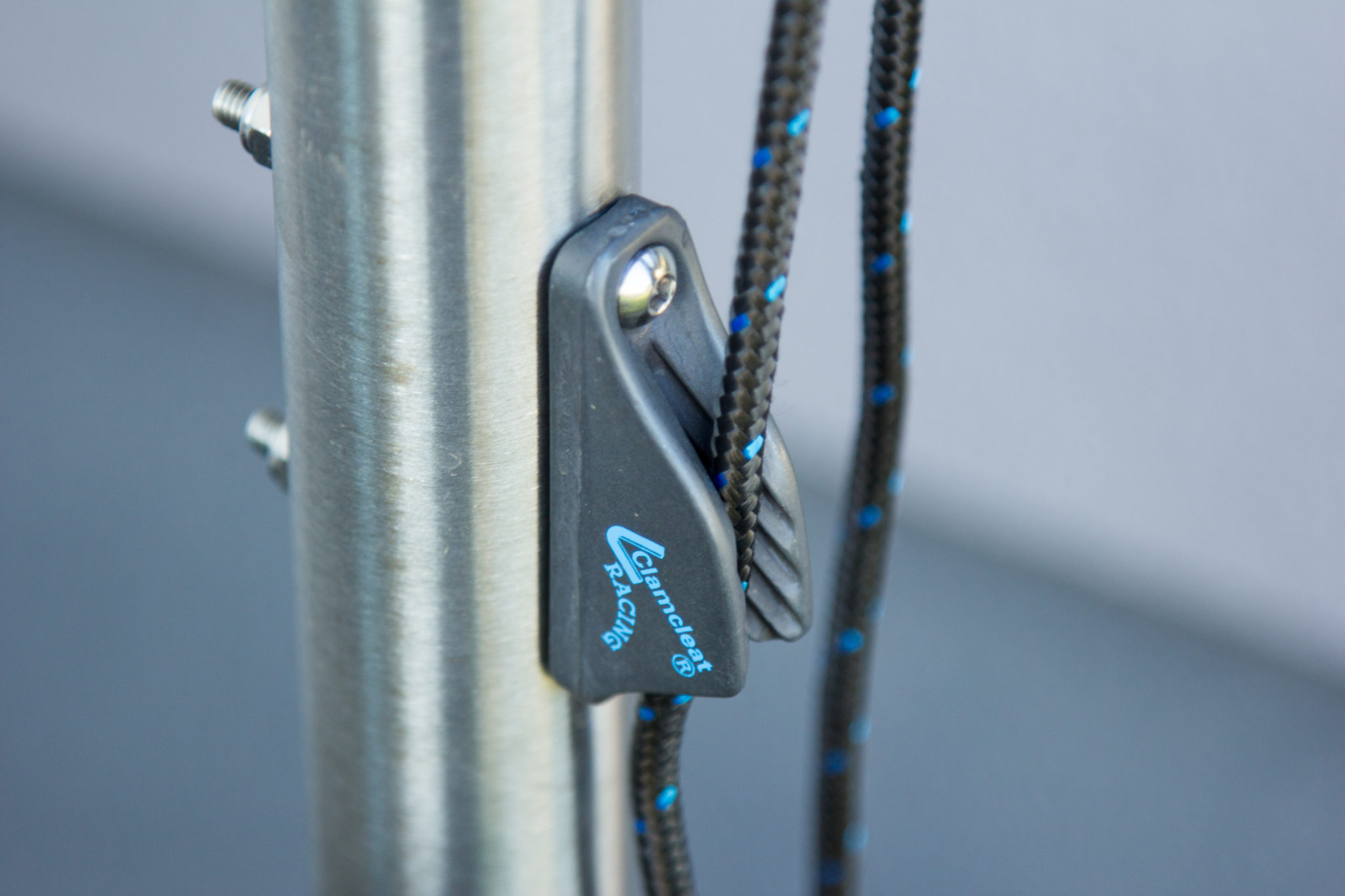
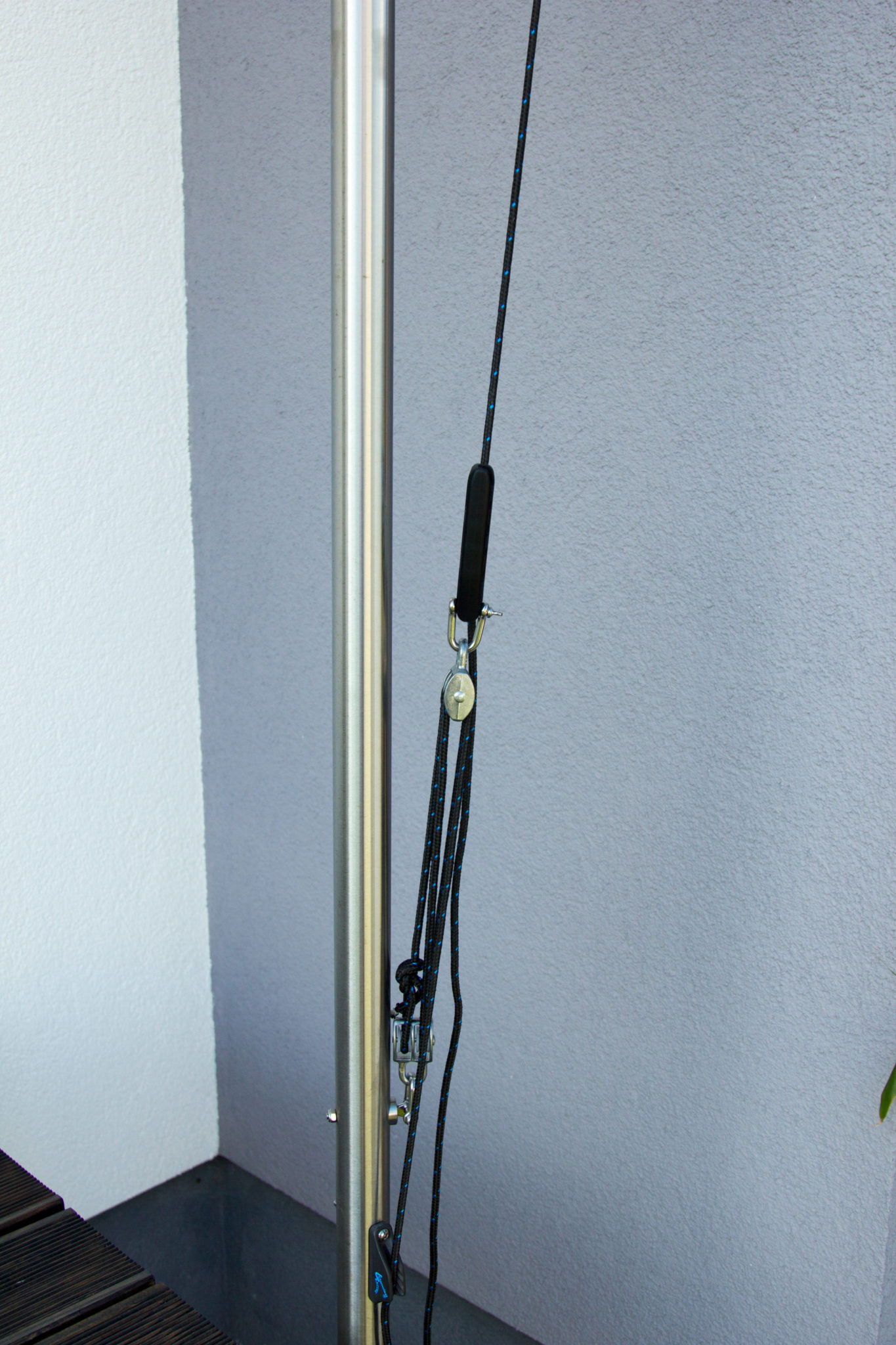
The Wantenspanner is not absolutely necessary, as I have subsequently integrated a pulley into the long axle rope in order to get as much tension as possible on it. However, the clamp makes the system more flexible and easier to assemble.
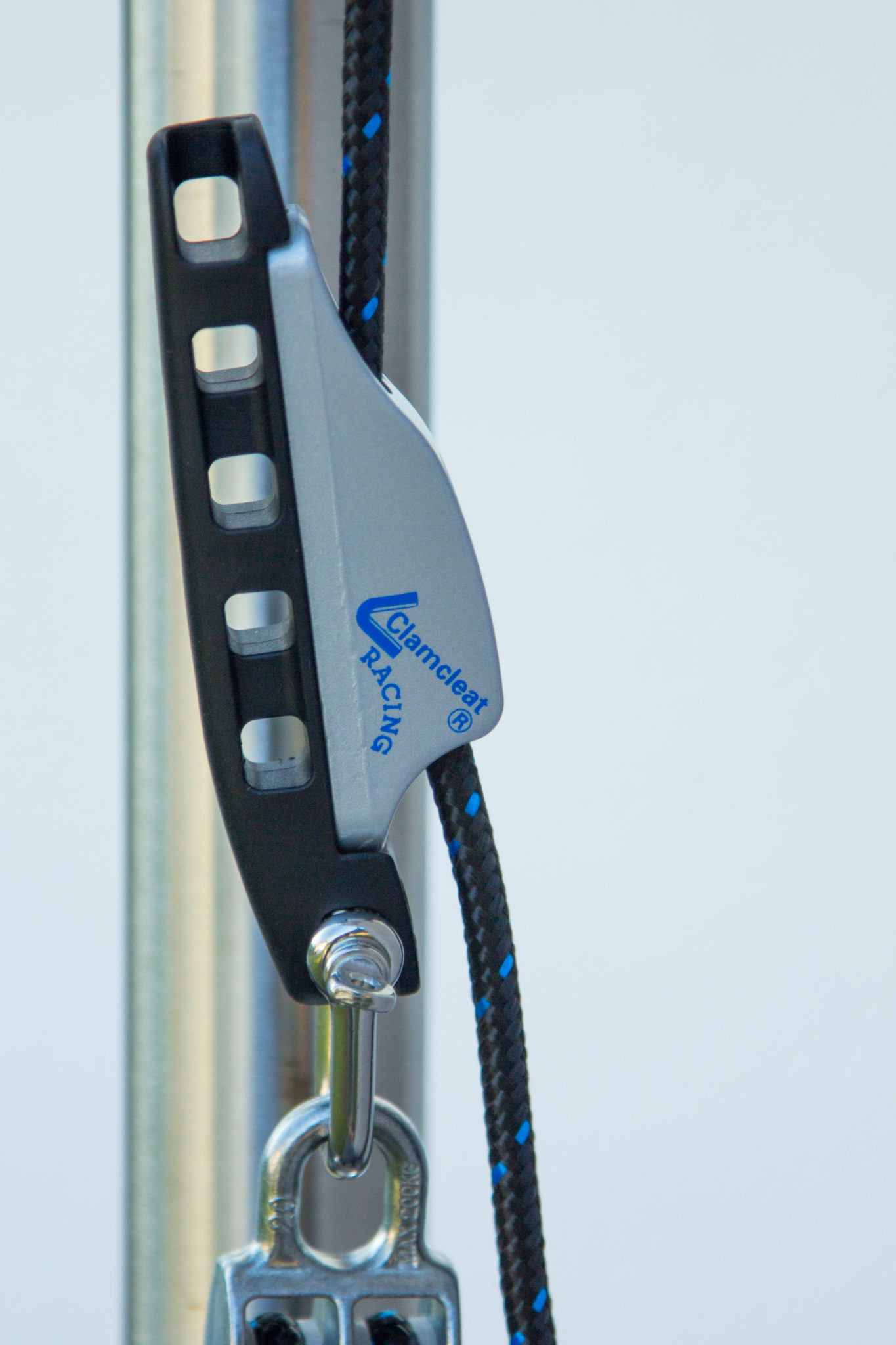
At the two free ends, a rope is first fastened for clamping, guided through the deflection and the aero-cleat. Here I needed a solution to attach the pulley to the tension rope. In addition, it should be easy to loosen and fasten. The Aero-Cleat is a good choice for this. one end is connected to the upper part of the pulley / or Niederholers. The clamping rope is guided through the clamp and easily pulled. Then tighten with the pulley / low-holer and bring it to suspense.


Order the appropriate cover cap immediately, so that no dirt or the like falls into the opening when the pipes are outside.

I have fastened the cover caps with second glue.